Let’s get going with a short series of tutorials dedicated to nonlinear control examples with Matlab/Octave implementation. First to go: unicycle.
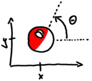
In order to describe the exact position and orientation of a robot moving on a planar surface you need only:
$latex q = \begin{pmatrix} x \\ y \\ \theta \end{pmatrix}$
The mathematical model for the unicycle is quite easy:
$latex \dot{q} = \begin{pmatrix} \dot{x} \\ \dot{y} \\ \dot{\theta} \end{pmatrix} = \begin{pmatrix} v \cos{\theta} \\ v \sin{\theta} \\ \omega \end{pmatrix} $
Ok, so first we will need a matlab function that returns this exact vector:
function dq = unicycle( t, q )
x = q(1);
y = q(2);
theta = q(3);
v = 1;
w = 1;
dq = [ v*cos(theta) ; ...
       v*sin(theta) ; ...
       w ];
and the simulation script:
function unicycle_test
[t,q] = ode45( @unicycle, 0:0.01:10, [5 4 pi/3] )
plot( q(:,1), q(:,2) )
Of course, you don’t need to create two separate files for those – you can place them together, just make sure that unicycle_test is on top and the name of the file is unicycle_test.m
What should be the result? Well, if the unicycle is travelling forward with velocity $latex v=1$ and steering left with velocity $latex \omega=1$ … a circle.
(placeholder for a plot)
Ok, let’s do the drunk driving now:
v=1
w= 0.1 * sin(t)
the steering wheel should now move left and right.
Ok, now is the time for the first feedback – let’s stabilise the angle to zero = let’s go straight to the right. First, set the speed to a constant value:
v=1
now for the angle… basically the last equation of motion reads:
$latex \dot{\theta} = \omega \rightarrow \text{angle evolution} = \text{control}$
so… you can substitute nearly anything for the control signal, including a function of $latex \theta$! So… what ODE stabilises itself and has a nice eigenvalue of -1? Hmm… $latex \dot{\theta} = -\theta$? Let’s enforce it with a control signal:
w = -theta
and if you by any chanve would like to go up:
w = pi/2 - theta
so generally it’s a task of:
w = r - theta
where r is a reference position or a signal.
(placeholder for a plot)
Ok, but that’s just a simple feedback, what about something more complex? Let’s create a control system that stabilises the robot to a specific point – (0,0) for start should be sufficient.
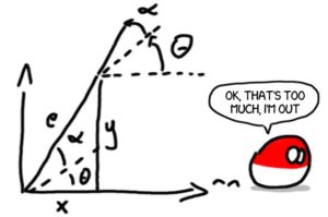
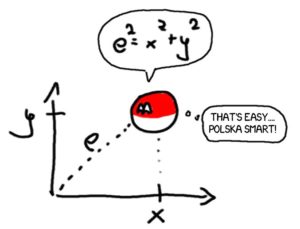
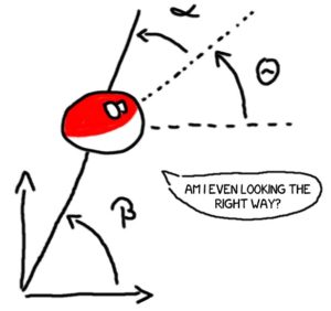
So how far are we? Distance in a straight line will be denoted as $latex e $ and is equal to $latex e = \sqrt{x^2 + y^2}$. And if we are a bit misaligned – to get straight to (0,0) we would need to rotate by $latex \alpha$… and then by $latex \beta$ to be exactly horizontal at the end.
Ok, so the task at hand is to get those signals to zero:
$latex \begin{matrix} e \rightarrow 0 \\ \alpha \rightarrow 0 \\ \beta \rightarrow 0 \end{matrix}$
using any type of controls $latex (v,\omega)$.
One of the better ways to do that is just to assume that those three variables are already STABLE (well, it is possible after all). How do we prove stability? Lyapunov! Just propose some Lyapunov (energy-like) function for the system and try to make it meet all the stability criteria.
Ok, so the most simple sketch for the energy is to grab all three and make them square: (a good energy-like function should be $latex >0$ and at the origin $latex =0$)
$latex V = \frac{1}{2} e^2 + \frac{1}{2} \alpha^2 + \frac{1}{2} \beta^2$
… why all the $latex \frac{1}{2}$ you ask? Well, in a moment we will be calculating derivatives and the best derivative of the type $latex \frac{d}{dt} t^2 = 2 t $ is of course $latex \frac{d}{dt} \frac{1}{2} t^2 = t$ – no numbers flying around anymore. In case we deal with function of time $x(t)$ we need to take into account the next level of derivatives $latex \frac{d}{dt} \frac{1}{2} x^2 = x \dot{x}$.
So… the Lyapunov function should be nicely decreasing during the motion and when it hits the 0 value it should stop and stick to it (well, that’s what you should hope for…). So is it falling like the hopes of every nation ever one minute after exit polls results?
\dot{V} = e \dot{e} + \alpha \dot{\alpha} + \beta \dot{\beta}
Now we need to calculate $latex \alpha, \beta$ and how they change… so:

From the triangle:
$latex \tan( \alpha+\theta ) = \frac{x}{y} \rightarrow \alpha = \text{atan}\frac{x}{y} – \theta$
$latex \beta = \alpha + \theta = \text{atan}\frac{x}{y}$
Remember that in Matlab there are two types of tangent function – tan(c) which works in 180 degrees radius and tan2(a,b) which works in the whole circle (where c=a/b).
(to be continued soon …)


where the next chapters?